CAD modeling never felt very intuitive to me. It still doesn’t. Reducing complex geometries to a set of basic shapes and transformations is hard. Finding a good workflow can help a lot.
OpenSCAD
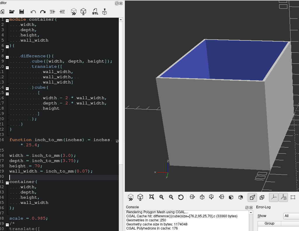
Autodesk’s Fusion 360 is the de facto standard that seemingly every ‘maker’ uses. Most alternatives work in more or less the same way. But then there’s OpenSCAD, which ditches the UI elements in favor of raw code. The syntax is basically Go and Python thrown into a blender.

Despite knowing about OpenSCAD for awhile, I kept putting off working with it. I wanted to have the conveniences that Fusion 360 gives you out of the box. Niceties like chamfers, bevels, and smoothing can make a huge difference in a model.
My fears were misguided.
Belfry OpenSCAD Library
The Belfry OpenSCAD Library (BOSL2) has support for most of the features I thought I would miss from Fusion 360. Plus, the quality of its wiki is extraordinary - stuffed with great examples.
So I’ll be relying on BOSL2 for the foreseeable future.
First Steps
The official tutorial for OpenSCAD is quite good. I went through about half of it before getting bored and bailing.
I want to learn OpenSCAD and reduce the pain of future modeling at the same time. How? Most of the models I’ve made involved screw holes - and screw holes are about as easy as CAD can get, so that’s where I started.
I want to make a jig so that I can consistently create holes that standard metric screws can cut their threads into.
As a starting point for screw sizes, I went off the specs. m2 screws are supposed to be 2 millimeters; m3 are supposed to be 3mm and so on. (But if you’re going to do 3d modeling, a set of calipers is an absolute must.)
Here’s what I worked out for a very basic test model.
include <BOSL2/std.scad>;

// for metric screws to self-cut threads in the 3d prints
module screwTest() {

    // All of these are in mm.
    // I just fiddled with them until it looked alright.
    depth = 5;
    height = 7;
    width = 55;

    // subtract the screw holes from the base
    difference() {

        // the base jig to contain all of the screw holes
        cuboid([width,height,depth]);

        // m2
        left(width * 0.35)
            cyl(d=2, h=depth);
        // m2.5
        left(width * 0.12)
            cyl(d=2.5, h=depth);
        // m3
        right(width * 0.05)
            cyl(d=3, h=depth);
        // m4
        right(width * 0.23)
            cyl(d=4, h=depth);
        // m5
        right(width * 0.43)
            cyl(d=5, h=depth);
    }
}

screwTest();
This gave me a decent jig, but we can make it look a lot cleaner and add labels.
include <BOSL2/std.scad>;

// for metric screws to self-cut threads
module screwTest() {
    depth = 5;
    height = 7;
    width = 55;

    difference() {
        cuboid(
	    [width,height,depth],
	    rounding=3, // smooths out the edges
	    edges="Z"   // leaves the top and bottom flat (for cleaner 3d printing)
	);

        // m2
        left(width * 0.35)union(){
            cyl(d=2, h=depth);

            up(depth * 0.5 - 1)
            fwd(1)
            left(7)
            text3d(
                "m2",
                size=3
            );
        }
        // m2.5
        left(width * 0.12)union(){
            cyl(d=2.5, h=depth);

            up(depth * 0.5 - 1)
            fwd(1)
            left(10.5)
            text3d(
                "m2.5",
                size=3
            );
        }
        // m3
        right(width * 0.05)union(){
            cyl(d=3, h=depth);

            up(depth * 0.5 - 1)
            fwd(1)
            left(7.5)
            text3d(
                "m3",
                size=3
            );
        }
        // m4
        right(width * 0.23)union(){
            cyl(d=4, h=depth);

            up(depth * 0.5 - 1)
            fwd(1)
            left(8)
            text3d(
                "m4",
                size=3
            );
        }
        // m5
        right(width * 0.43)union(){
            cyl(d=5, h=depth);

            up(depth * 0.5 - 1)
            fwd(1)
            left(8.5)
            text3d(
                "m5",
                size=3
            );
        }
    }
}

screwTest();
So much better.
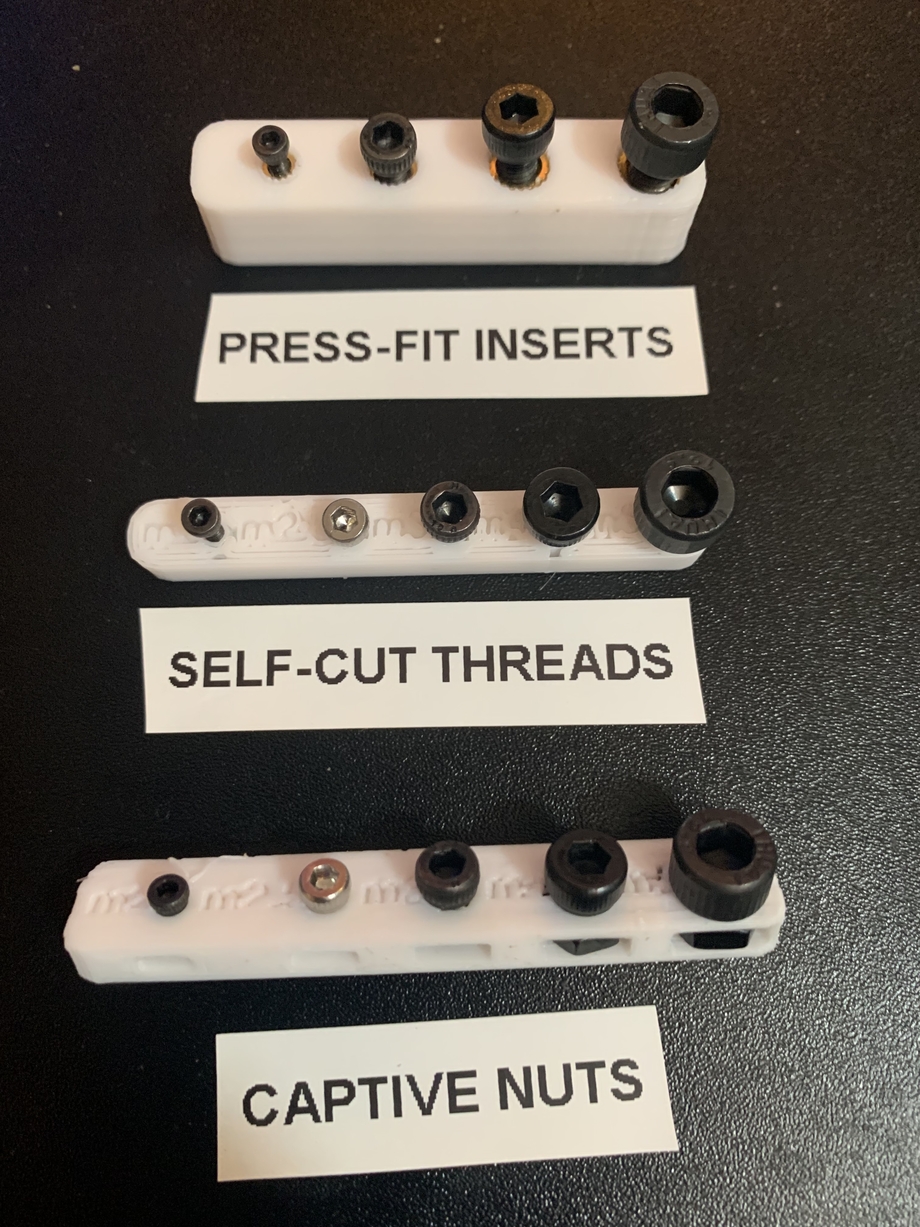
With that as a base, I created additional jigs. One to size out how to make slots for captive nuts. One to size out these press-fit inserts I bought and never used.
Captive nuts are when you put a nut inside the plastic itself and screw into it. Since nuts are usually much stronger than 3d printed plastic, using a captive nut can really increase the strength of a model.
Press-fit inserts are female-threaded pieces of metal that you heat up and push into the plastic. The idea is that the plastic will melt around the insert and hold it tight after cooling.
Iteration
The current versions of any of these: https://github.com/matt-fff/scadlib
With these basic jigs set up, I could actually test them on the 3d printer.
So comes the iteration loop:
- Print the jig.
- Test the hole sizes.
- Tweak the SCAD file.
- Repeat.
All of the jig holes need to be large enough that they’re easy to use, but none of the holes can be too large.
Press-fit insert jig: The holes need to be small enough that the plastic will fully conform to the insert after it cools.
Captive nut jig: The holes need to be small enough to hold the nut steady as a screw is driven into it.
Self-cutting screw jig: The holes need to be small enough that the screws cut their threads in the plastic.

It took a lot of iterations, but I finally settled on values that can reliably reproduce ideal screw sizes for my workflow. I created “official” screw modules so that I can reuse them in new SCAD files.
include <BOSL2/std.scad>;

module m2_hole(height, self_cut=true, anchor=CENTER) {
    diam = (self_cut) ? 2.2 : 3;
    cyl(
        d=diam,
        h=height,
        anchor=anchor
    );
}
...
module m5_hole(height, self_cut=true, anchor=CENTER) {
    diam = (self_cut) ? 5 : 6;
    cyl(
        d=diam,
        h=height,
        anchor=anchor
    );
}

module m2_captive_nut(height, inset=2, anchor=CENTER) {
    width = 4.5;
    cuboid(
        [width, width + inset + 1.5, height],
        anchor=anchor
    );
}
...
module m5_captive_nut(height, inset=3, anchor=CENTER) {
    width = 9;
    cuboid(
        [width, width + inset + 1.5, height],
        anchor=anchor
    );
}
Reusing the screw things
I now have a library of screw holes that I know will work with my screws and 3D printing process. Now what?
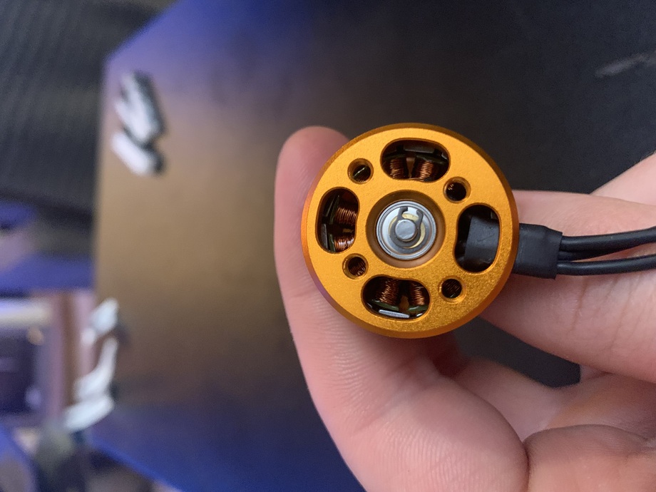
I have four brushless motors that I plan on using soon, so it makes sense to start there. Each motor has four m3 screws arranged around its core.

As you can see, the screw holes are somewhat asymmetric. There’s an additional 3mm between the wider set of screws.
A tip for finding the distance between two screw holes:
- Measure the distance between the outer edges of the holes
- Measure the distance between the inner edges of the holes
- Add the distances together and divide by two.
include <BOSL2/std.scad>;
use <scadlib/screws.scad>;

module screw_holes(height, anchor=CENTER) {
    width1 = (13 + 18.5) / 2;
    width2 = (16 + 21.5) / 2;
    fwd(width1/2)
        m3_hole(height, self_cut=false, anchor=anchor);
    back(width1/2)
        m3_hole(height, self_cut=false, anchor=anchor);
    zrot(90)union() {
        fwd(width2/2)
            m3_hole(height, self_cut=false, anchor=anchor);
        back(width2/2)w
            m3_hole(height, self_cut=false, anchor=anchor);
    }
}

module air_hole(height) {
    cuboid(
        // idk why the height needs bumped
        [8, 4, height * 1.01],
        anchor=BOTTOM,
        edges="Z",
        rounding=2
    );
}

module air_holes(height) {
    width = (13 + 22.5) / 2;
    fwd(width/2)air_hole(height);
    back(width/2)air_hole(height);
    zrot(90)union() {
        fwd(width/2)air_hole(height);
        back(width/2)air_hole(height);
    }
}


module motor_mount(
    motor_diam=28,
    shell_thickness=1.5,
    shell_lip=5,
    wire_width=7,
){
    double_thick = shell_thickness * 2;
    difference() {
        // shell
        cyl(
            d=motor_diam + double_thick,
            h=shell_lip + shell_thickness,
            anchor=BOTTOM,
            chamfer2=1
        );
        up(shell_thickness)union() {
            // motor negative space
            cyl(
                d=motor_diam,
                h=shell_lip + shell_thickness,
                anchor=BOTTOM,
                chamfer=1
            );
            // wire negative space
            fwd(shell_thickness)cuboid(
            [
                wire_width,
                motor_diam,
                shell_lip + shell_thickness
            ], anchor=BOTTOM);

            // holes
            down(shell_thickness)union() {
                // m3 screw holes
                zrot(-45)
                    screw_holes(shell_thickness, anchor=BOTTOM);
                // air holes
                air_holes(shell_thickness);
            }
        }
    }
}

motor_mount();
The resulting model:
I printed out the model to make sure it actually matched the motors. Perfect fit.
